clock

Saturday 25 May 2013

Where USB Memory Sticks are Born?

Where USB Memory Sticks are Born

In January, I had the fortune of being a keynote speaker at LCA2013. One of the tchotchkes I received from the conference organizers was a little USB memory stick.


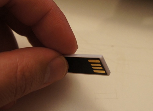
I thought it was a neat coincidence that I was in a factory that manufactured exactly such memory sticks about a week before the conference. In fact, I managed to score a rare treat: the factory owner gave me a sheet of raw chip-on-flex, prior to bonding and encapsulation, to take home.
The USB sticks start life as bare FLASH memory chips. Prior to mounting on PCBs, the chips are screened for capacity and functionality. Below is a photo of the workstation where this happens:

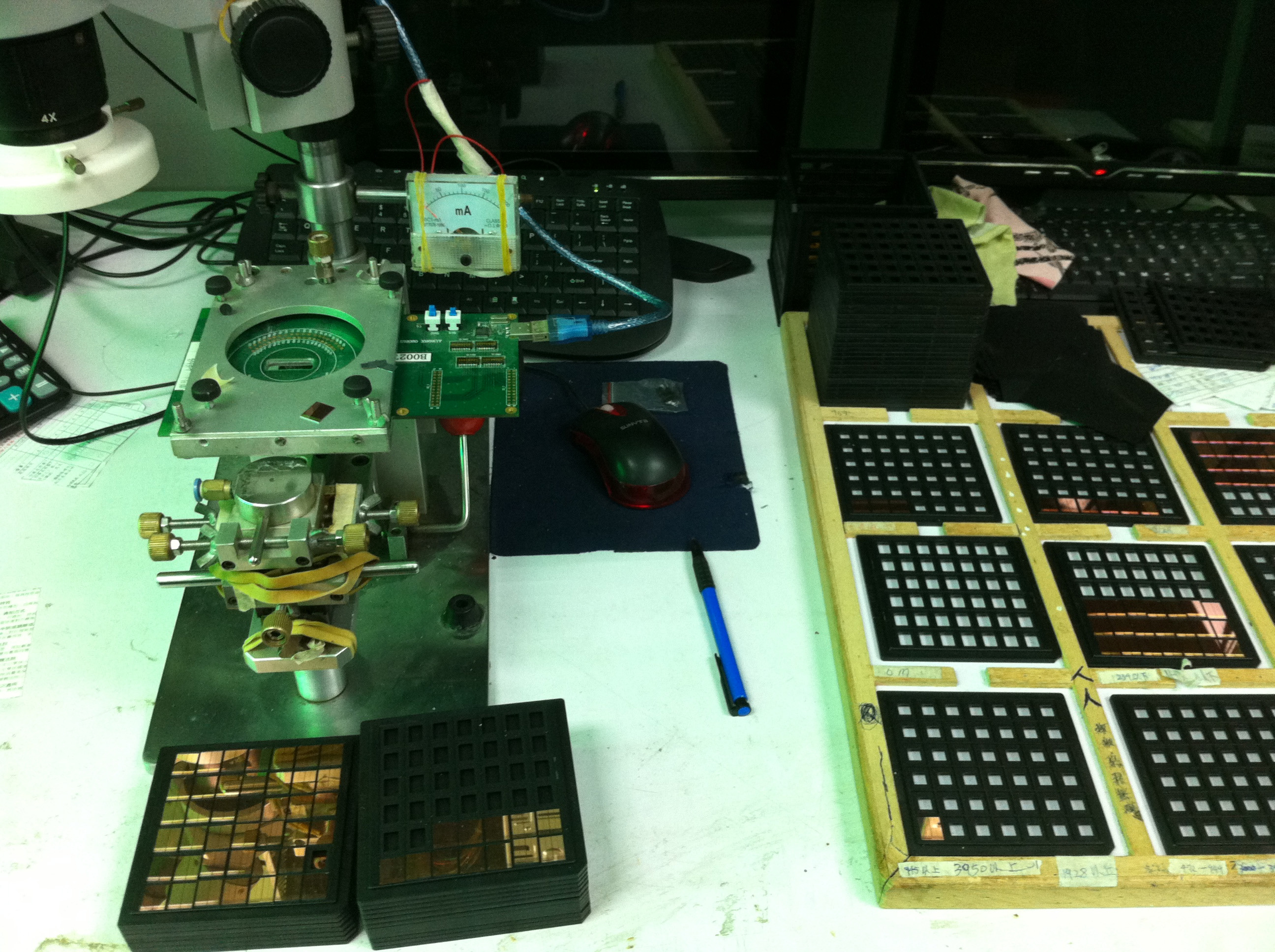
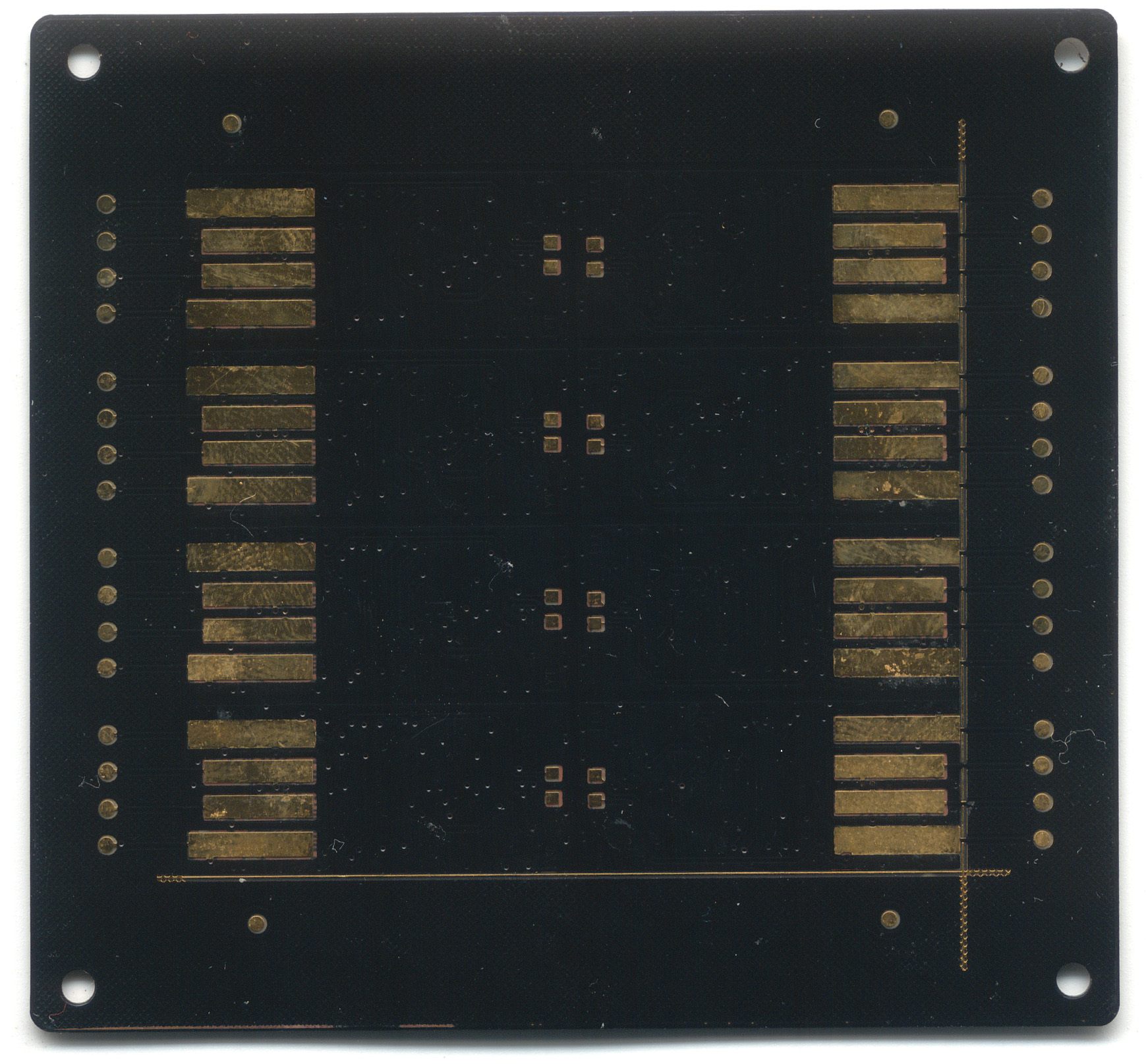
In the image, you can see stacks of bare-die FLASH chips, awaiting screening with a probe card. I love the analog current meter and the use of rubber bands to hold it all together. The probe card has tiny needles on it that touch down on microscopic (less than 100-micron square) contacts on the chip surfaces. Below is what a probe card looks like.

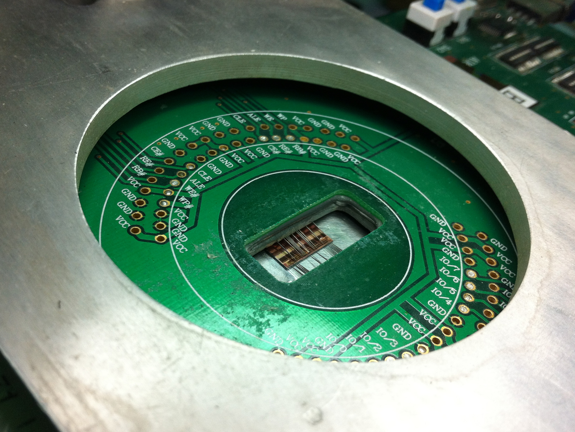
Below is an image through the microscope on the micro-probing station, showing the needles touching down on the square pads at the edge of the FLASH chip’s surface.

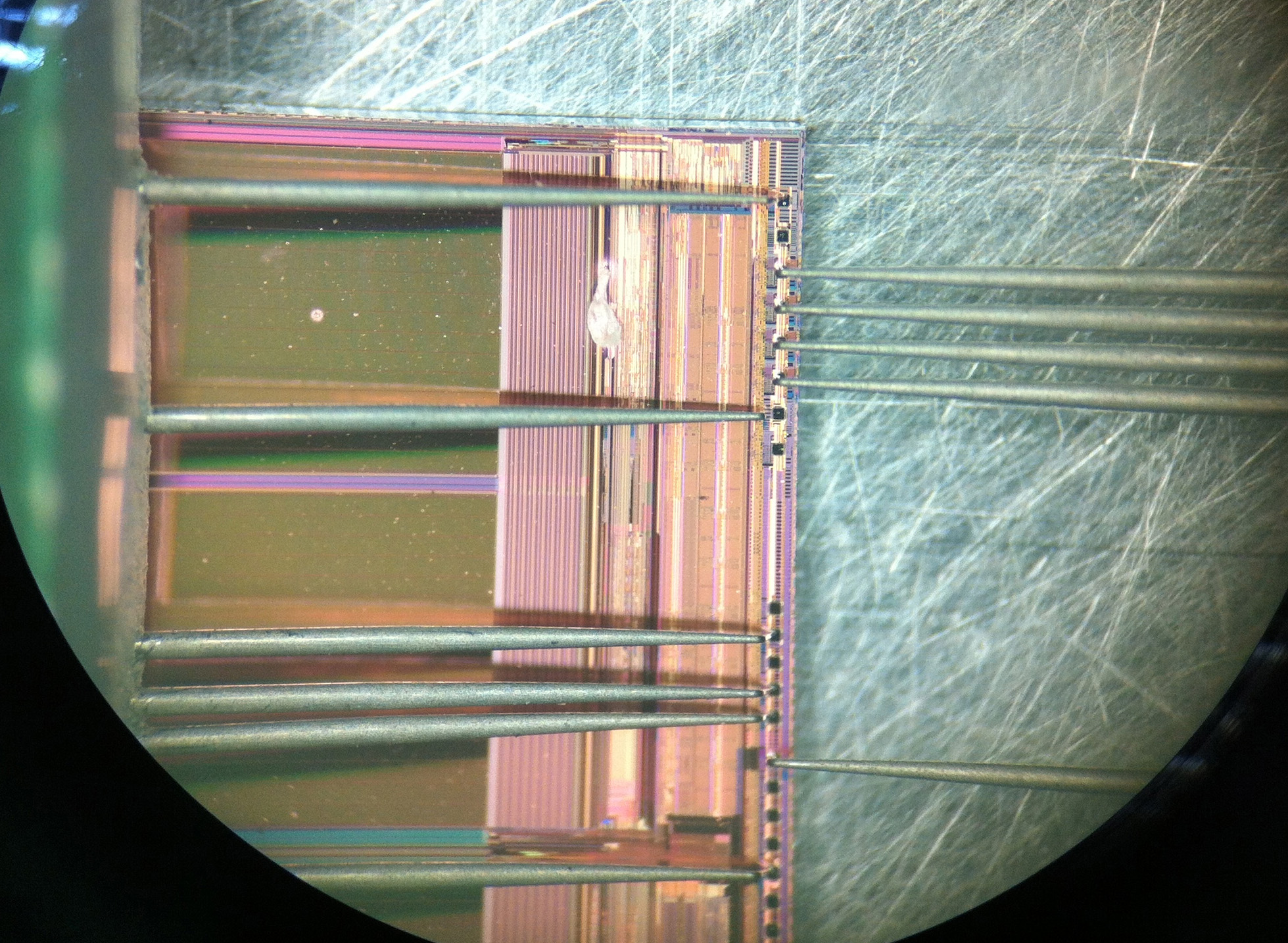
Interestingly, this all happens in an absolutely non-clean-room environment. Workers are pretty much handling chips with tweezers and hand suction vises, and mounting the devices into these jigs by hand.
Once the chips are screened for functionality, they are placed by hand onto a PCB. This is not an unusual practice, pretty much every value-oriented wirebonding facility I’ve visited relies on the manual placement of bare die. The photo below shows a controller IC being placed on a panel of PCBs. The bare die are in the right hand side of the photo, sitting in the beige colored waffle pack.

The lady is using some sort of tool made out of hand-cut bamboo. I still haven’t figured out exactly how they work, but every time I’ve seen this process they are using what looks like a modified chopstick to place the chips on the board. My best guess is that the bamboo sticks have just the right surface energy to adhere to the silicon die, such that silicon will stick to the tip of the bamboo rod. A dot of glue is pre-applied to the bare boards, so when the operator touches the die down onto the glue, the surface tension of the glue pulls the die off of the bamboo stick.
It’s trippy to think that the chips inside my USB stick were handled using modified chopsticks.

The chips are then wirebonded to the board using an automated bonding machine which uses image recognition to find the location of the bond pads (this is part of the reason they can get away with manual die placement).
(view in HD)
The first half of the video above starts out with the operator pulling off and replacing a mis-bonded wire by hand, and re-feeding the wire into the machine. Given that these wires are thinner than a strand of hair, and that the bonding pads are microscopic, this is no mean feat of manual dexterity.
Here’s a scan of the partially-bonded but fully die-mounted PCB that I was given as a memoir from my visit (I had since crushed some of the wire bonds). The panel contains eight USB sticks, each consisting of a FLASH memory chip and a controller IC that handles the bridging between USB and raw FLASH, a non-trivial task that includes managing bad block maps and error-correction, among other things. The controller is probably an 8051-class CPU running at a few dozen MHz.


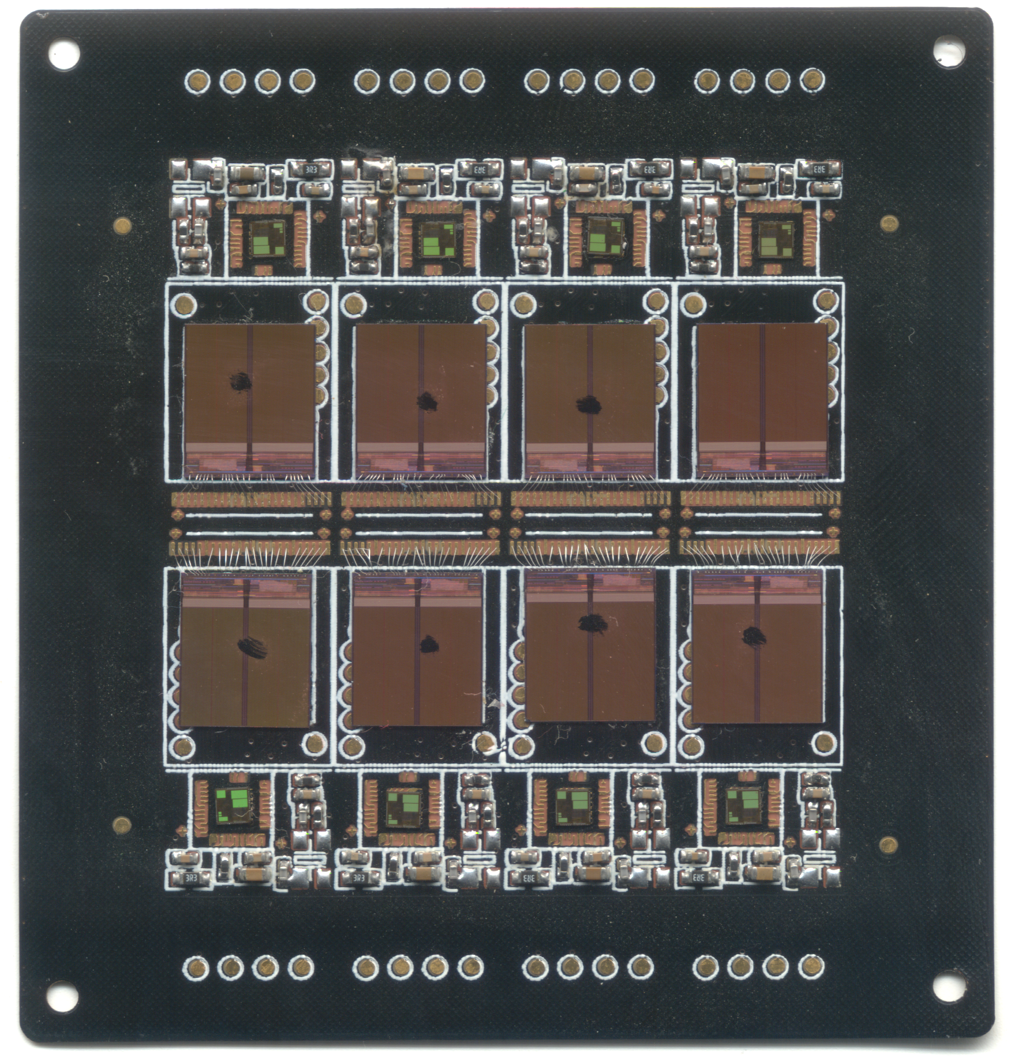
Once the panels are bonded and tested, they are overmolded with epoxy, and then cut into individual pieces, ready for sale.
Interestingly, the entire assembly prior to encapsulation is flexible. The silicon chips have been thinned down by grinding off their back sides to the point where they can tolerate a small amount of flexing, and the PCB is also so thin, it is flexible.

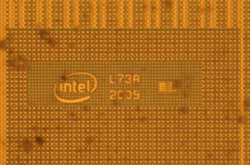
For those of you interested in this kind of thing, here’s the die marking from the FLASH chip; apparently it is made by Intel:

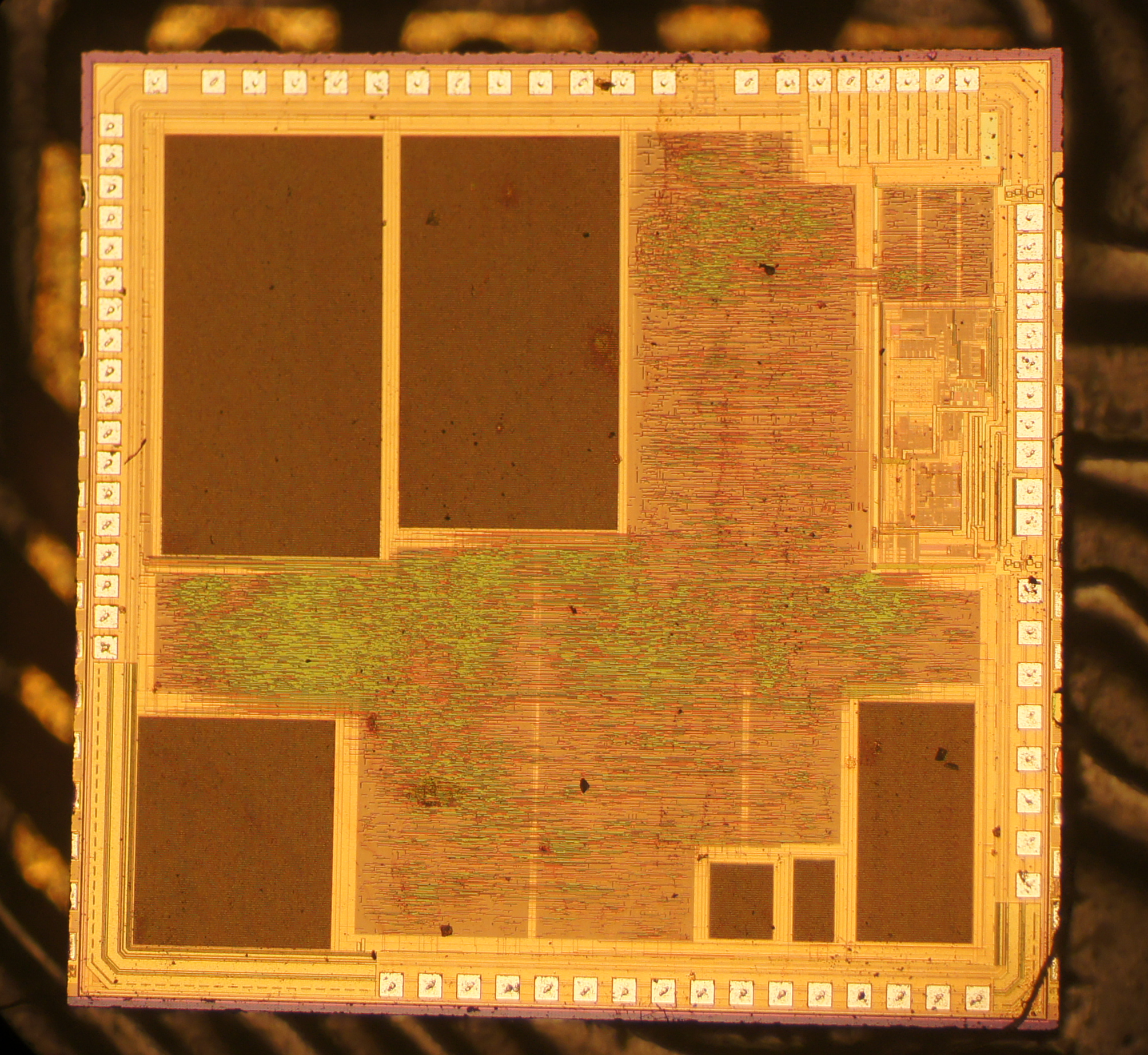
Here is also a die shot of the controller chip:

And now you know where those tiny USB thumb drives are born.
Thanks to David Cranor for contributing images. Images used with permission.
PS: chopsticks

A Simple SMS Based Controlling Different Industrial Machines Using GSM Mobile and microcontroller 8051

A simple SMS Based Controlling Machines Using GSM Mobile and microcontroller 8051

SMS Based Controlling Different Industrial Machines Using GSM Mobile and microcontroller 8051
This project (interfacing mobile phone with microcontroller 8051 for machines control through SMS) has many important other applications and can be used to control Switch ON or OFF any machines at far off places using a gsm modem by sending sms through the communication between the mobile and the embedded devices (microcontroller 8051).This remote control of appliances is possible through Embedded Systems. The use of “Embedded System in Communication” has given rise to many interesting applications that ensures comfort and safety to human life. The microcontroller is interfaced with GSM Modem in mobile phone via MAX232 level convertor. The microcontroller project is designed to allow easy use of a mobile phone to control appliances or machines at any far location may be in industry or at home. Using a mobile phone the development of the control system will be carried out using SMS. This will communicate with another mobile phone, which in turn controls the devices attached to microcontroller modules. moving message display using 8051 microcontroller When the action has been carried out then a response is sent to the user. The use of mobile phones to remotely control an appliance control system. The microcontroller would then control the device based on the information given to it.This post also relates to the project of microcontroller interfacing with lcd and gsm to display the msg sent to interfaced gsm,sms based on off control of a motor throgh 8051 micro controller ,methodology of designing a gsm base noticeboard and motor control through sms circuit diagram .

The devices are connected to the 8051 microcontroller using relays and optocouplers. These relay are controlled through software to switch ON or OFF the device as required. For every message received to microcontroller through mobile phone in form of SMS, the controller will check for the valid and pre-define formate. If the message is correct the controller will perform the operation. microcontroller interfacing with lcd and gsm to display the msg sent to interfaced gsm

The hardware board contains microcontroller AT89c52 at the heart of the system. The microcontroller is interfaced with GSM Modem of mobile phone via MAX232 level convertor. It is used to convert RS232 voltage levels to TTL voltage levels. display the message in notice board with the help of mobile 8051 project gsm architecture based motor on and off circuit diagram

The AT89C52 is a low-power, high-performance CMOS 8-bit microcomputer with 8K bytes of Flash programmable and erasable read only memory (PEROM). The device is compatible with the industry-standard 80C51 and 80C52 instruction set and pin out. The on-chip Flash allows the program memory to be reprogrammed in-system or by a conventional non-volatile memory programmer which provides a highly-flexible and cost-effective solution to many embedded control applications.A GSM modem is a wireless modem that works with a GSM wireless network. A wireless modem behaves like a dial-up modem. The main difference between them is that a dial-up modem sends and receives data through a fixed telephone line while a wireless modem sends and receives data through radio waves. Like a GSM mobile phone, a GSM modem requires a SIM card from a wireless carrier in order to operate.controlling machines using gsm mobile sms services
Generally, computers use AT commands to control modems. Reading of message from the SIM card inserted into the modem is done by sending the appropriate AT command to the modem.
The MAX232 is a dual driver/receiver that includes a capacitive voltage generator to supply EIA-232 voltage levels from a single 5-V supply. Each receiver converts EIA- 232 inputs to 5-V TTL/CMOS levels. Each driver converts TTL/CMOS input levels into EIA-232 levels.
SMS Based Controlling Machines Using GSM Mobile and microcontroller 8051 tutorial tracker gps gsm


GSM Modem, which works at RS-232 voltage levels, logic 1 varies from -3 to -15 volts and logic 0 from +3 to +15 volts. The microcontroller which works on TTL logic levels, logic 1 is +5 volts and logic 0 is 0 volts. Therefore to interface the two we use a MAX 232 driver IC.tutorial tracker gps gsm


AT-Command set
The following section describes the AT-Command set. The commands can be tried out by connecting a GSM modem to one of the PC’s COM ports. Type in the test-command, adding CR + LF (Carriage return + Line feed = \r\n) before executing. Table gives an overview of the implemented AT-Commands in this application. The use of the commands is described in the later sections.

AT-Command set overview

The AT Command
Description of Commands
AT
Check if serial interface and GSM modem is working.
ATE0
Turn echo off, less traffic on serial line.
AT+CNMI
Display of new incoming SMS.
AT+CPMS
Selection of SMS memory.
AT+CMGF
SMS string format, how they are compressed.
AT+CMGR
Read new message from a given memory location.
AT+CMGS
Send message to a given recipient.
AT+CMGD
Delete message.

GSM Modem is used to receive message from the authorized user. This GSM modem requires a SIM card from a wireless carrier in order to operate. This SIM number is contact number of the receiving section.
First, the microcontroller have to send “AT” A response "OK" should be returned from the mobile phone or GSM modem. Now the microcontroller will send "AT+CPIN?". The AT command "AT+CPIN?" is used to query whether the mobile phone or GSM modem is waiting for a PIN (personal identification number, i.e. password). If the response is "+CPIN: READY", it means the SIM card is ready for use. After this, various AT commands depending on the used modem’s instruction set are send to modem and responses are received. This process is very useful in testing GSM modems.
, the AT89S52 is designed with static logic for operation down to zero frequency and supports two software selectable power saving modes. The Idle Mode stops the CPU while allowing the RAM, timer/counters, serial port, and interrupt system to continue functioning. The Power-down mode saves the RAM con-tents but freezes the oscillator, disabling all other chip functions until the next interrupt. In this project MODEM is communication with the microcontroller through serial port, the microcontroller will send the commands to the modem through RS 232.and the data is read through serial port therefore to make compatible computer serial port with microcontroller serial port we are using the RS 232 converter.A GSM network is composed of several functional entities, whose functions and interfaces are specified. Figure 1 shows the layout of a generic GSM network. The GSM network can be divided into three broad parts. The Mobile Station is carried by the subscriber. The Base Station Subsystem controls the radio link with the Mobile Station. The Network Subsystem, the main part of which is the Mobile services Switching Center (MSC), performs the switching of calls between the mobile users, and between mobile and fixed network users. The MSC also handles the mobility management operations. Not shown is the Operations and Maintenance Center, which oversees the proper operation and setup of the network. The Mobile Station and the Base Station Subsystem communicate across the Um interface, also known as the air interface or radio link. 8051 provides a transmit channel and a receive channel of serial communication. The transmit data pin (TXD) is specified at P3.1, and the receive data pin (RXD) is at P3.0. All modes are controlled through SCON, the Serial control register. The timers are controlled using TMOD, the Timer mode register, and TCON, the Timer control register. free circuit electronic gsm controller system ,controlling machines using gsm mobile sms services gsm interfacing with microcontroller 8051

Interfacing ADC0808 to AT89C51 Microcontroller

 WARNING: Before proceeding, I'm not responsible for any damage or short circuit on your circuit. The code and circuit is tested and verified working.

 AIM: To help for understand the c language and embedded systems working in simple way.


What is ADC?
Its basically a device having internal comparators and resistors arrangement which gives you digital output value of a corresponding input voltage.
ADC stands for Analog to Digital Converter.

ADC0808 is 8bit conversion system. For more details read the datasheet.
Converts any analog input into 1byte digital output.
It has all-together 8 analog inputs (IN0 to IN7).
Each analog input has an address which is set through control signals A, B, C.
Clock has to be provided for conversion rate.
Faster clock faster conversion.
They recommend 600KHz clock.
I used 555timer at 687Hz which is good enough to convert data on one analog input.
LM324 is used so that there is no drawing current or loading effect on the input side.

First construct this schematic below on breadboard or pcb. (schematic is tested )


Based on my previous design on 16x2 LCD interface to AT89C51 I'm making advantage of it to display my adc data onto it. But this time I'm using separate header files.

After constructing the above schematic. Lets proceed with programming.
Make project in keil software selecting 89c51 microcontroller.
Now next, right click on target 1 and add a group "headers".
Now create this headers files as told below:

1. To make header files create a new file - > save the file in format "filename.h"
2. Add the files to header group in project workspace.
3. Do the above 2 steps for below codes.
This helps in debugging faster.

Check out the image below how its done. (I made group of source and header files)


Now add this files as show above. Keep them all blank and with same names.
Now open the blank 16_2lcd.h file and enter the code below and save it:

///////////////////////////////////////////INSIDE 16_2lcd.h   FILE////////////////////////////////
#include "AT89X51.H"
#include "delay.h"
#include "stdio.h"
#define RW P0_1
#define RS P0_0
#define EN P0_2
#define DATA P2

int lcd_inst(void);     //Instruction sel
int lcd_data(void);      //Data sel
int lcd_latch(void);       //Latch the bus
int lcd_write_str(char *str, int str_len, int line);       //Write string
int lcd_write_int(int num, int num_len, int line); //Write integer
int lcd_write_float(float num, int num_length, int line); //Write float
int lcd_clear(void); //clears lcd screen
int lcd_linsel(int line);    //Lcd line sel
int lcd_initialize(void);    //Initialize the LCD
///////////////////////////////////////////INSIDE 16_2lcd.h   FILE END////////////////////////////////

 Now open the blank adc0808.h file and enter the code below and save it:

///////////////////////////////////////////INSIDE adc0808.h  START////////////////////////////////

#include "AT89X51.H"
#include "delay.h"


#define OE P3_0
#define ALE P3_1
#define A P3_2
#define B P3_3
#define C P3_4

#define ADC_DATA P1


int read_ain(int ain_pin);//Reads ext. Analong in
int set_analongin(int ain_pin);// Sets in0 to in7 pin select.

///////////////////////////////////////////INSIDE adc0808.h  END////////////////////////////////

Now open the blank  delay.h file and enter the code below and save it:
///////////////////////////////////////////INSIDE delay.h  START////////////////////////////////
 void delay(int n); //Universal delay routine
///////////////////////////////////////////INSIDE delay.h  END////////////////////////////////
Now open the blank  16_2lcd.c  file and enter the code below and save it:
///////////////////////////////////////////INSIDE 16_2lcd.c START////////////////////////////////
#include "16_2lcd.h"

int lcd_inst(void)     //Instruction select
{
    RS=0;
    RW=0;
    return 0;
}

int lcd_data(void) // Data select
{
     RS=1;
     RW=0;
     return 0;
}

int lcd_latch(void) // Latch routine
{
            EN=1;
            delay(100);
            EN=0;
            delay(100);
            EN=1;
            delay(100);
            return 0;
}

int lcd_initialize(void)    //Initialize the LCD
{
             RS=0; 
             RW=0;
             EN=1;
             delay(100000);
             lcd_inst();
             DATA=0X38;     //This instruction will Enable 8-bit Databus, Set 2 lines, and Select font size 5x7
             lcd_latch();
             lcd_latch();
             lcd_latch();
             lcd_latch();
             DATA=0X0c;       //It will display the characters, will not display the cursor
             lcd_latch();
             DATA=0X80;    //Set cursor on line 1
             lcd_latch();
             DATA=0X01;       //Clear screen
             lcd_latch();
             lcd_data();
             return 0;
}

int lcd_clear(void)
{
            lcd_inst();
             DATA=0X01;       //Clear screen
             lcd_latch();
             lcd_data();
            return 0;
}
int lcd_linsel(int line)    //Lcd line sel
{
    lcd_inst();
    if(line==1)
    {
             DATA=0X80;    //Set cursor on line 1
             lcd_latch();          
    }
    if(line==2)
    {
             DATA=0XC0;    //Set cursor on line 2
             lcd_latch();          
    }
    lcd_data();
}

int lcd_write_str(char *str,int str_len, int line)
{
    int i;
    lcd_linsel(line);    //Lcd line sel
    lcd_data();
    for(i=0;i<=str_len-1;i++)
    {
            DATA=str[i];
            lcd_latch();
    }
    return 0;
}

int lcd_write_int(int num,int num_len,int line) //Write integer
{

    int i;
    char str[16];
    str[0]=0;
    str[1]=0;
    str[2]=0;
    lcd_linsel(line);    //Lcd line sel
    lcd_data();
    sprintf(str,"%3.0d",num);
    for(i=0;i<=num_len-1;i++)
    {
            DATA=str[i];
            lcd_latch();
    }
    return 0;
}

int lcd_write_float(float num,int num_len,int line) //Write integer
{

    int i;
    char str[16];
    str[0]=0;
    str[1]=0;
    str[2]=0;
    lcd_linsel(line);    //Lcd line sel
    lcd_data();
    sprintf(str,"%3.3f ",num);
    for(i=0;i<=num_len-1;i++)
    {
            DATA=str[i];
            lcd_latch();
    }
    return 0;
}
///////////////////////////////////////////INSIDE 16_2lcd.c END////////////////////////////////


 Now open the blank  adc0808.c  file and enter the code below and save it:
///////////////////////////////////////////INSIDE adc0808.c START////////////////////////////////
#include "adc0808.h"


int read_ain(int ain_pin)// Reads adc value at given pin
{
  int num;
  ADC_DATA=0xFF;
  OE=0;
  set_analongin(ain_pin);
  OE=1;
  num=ADC_DATA;
  OE=0;
  return num;
}

int set_analongin(int ain_pin)// Sets in0 to in7 pin select.
{
      ALE=0;
    switch(ain_pin)
    {
        case 0: A=0;B=0;C=0;break;
        case 1: A=1;B=0;C=0;break;
        case 2: A=0;B=1;C=0;break;
        case 3: A=1;B=1;C=0;break;
        case 4: A=0;B=0;C=1;break;
        case 5: A=1;B=0;C=1;break;
        case 6: A=0;B=1;C=1;break;
        case 7: A=1;B=1;C=1;break;
        default:break;
    }
    ALE=1;
      delay(100);
      ALE=0;
    return 0;
}
///////////////////////////////////////////INSIDE adc0808.c END////////////////////////////////
 Now open the blank  delay.c  file and enter the code below and save it:

///////////////////////////////////////////INSIDE delay.c START////////////////////////////////
 #include "delay.h"


 void delay(int n) //Universal delay routine
{
 int i=0,j=0;
 for(i=0;i<=n;i++)
 for(j=0;j<=10;j++);
}
 ///////////////////////////////////////////INSIDE delay.c END////////////////////////////////
Now open the blank  main.c  file and enter the code below and save it:
  ///////////////////////////////////////////INSIDE main.c START////////////////////////////////
//Programmed by Macjan Camilo Fernandes
//Test Version 1.0.0

#include "16_2lcd.h"
#include "adc0808.h"
#include "delay.h"
#include "REGX51.H"
#include "stdio.h"

int main(void)
{
    float calc;
    int test,i;
    char mac[16];
P3=0;
 //Initialize LCD
 lcd_initialize();
 lcd_clear();
 //write title
//i can be from 0 to 7 since only 8 channel select
  i=3; // to read analog input at pin in3 of ADC0808
  sprintf(mac,"ADC Data %d in V",i+1);
  lcd_write_str(mac,15,1);       //Write string
 while(1)
 {
   test=read_ain(i); //reads analog input of channel i
   calc= test*0.0195; //calculates voltage for vref=5v vref-=0v
   delay(100);
  //Write_adc data on LCD
  lcd_write_float(calc,5,2);         //Write adc data
 }


return 0;
}
  ///////////////////////////////////////////INSIDE main.c END////////////////////////////////
After doing this above process. Compile and program the microcontroller.
Check the ADC value. 
The adc0808.h and adc0808.c was done by me so that you can make use of adc easily if you include this header files in main code as shown above.
Use this function   
int read_ain(int ain_pin);// Reads adc value at given pin
eg: x=read_ain(3); 
This instruction above will store value of adc input IN3 value into x variable which you can then process into your desired calculations.
You can go though the header files and source files for deeper details.

Some snapshots of my demo for one ADC input at ADC0808 in3


All the best to you,
Will be updating my blog with lots of interfaces. Be in touch.
Thank you for reading,

PIR Motion Dectector based Automatic Staircase Light


!!WARNING!! High Voltage Connections inside. Beware during the process. I am not responsible for any short circuit of damage to you. Do it on your own risk.

The circuit above has been tested and is working well.

 
Power Saving has been the biggest issue so far, Sometimes people forget to turn off the lights on sta
ircase at night. Imagine a skyscraper of 100floors. Staircase must be consuming around 500W+ of power itself during night time.

Automatic PIR Light technology helps to save power by 60% during night time.

A normal PIR light costs like around Rs.1000 to 15000. I will explain you the circuits behind it. But use it for your own purpose. Do not SELL.


Test included: 45W mercury bulb. 230V AC

This circuits has two loops. One loop contains the low voltage PIR sensor circuit. The other loop contains 230V circuit.

The low +5V is obtained by a simple circuit including a Bridge rectifier.(D1,D2,D3,D4) Coupled with capacitor filter C1 to bypass any AC ripples in dc output from the bridge rectifier.

LM7805 Regulator IC is a linear based regulator system. Standardized to give +5V output at any input >+5v to +18v at 1A current max support.

The PIR (Passive Infra Red) Sensor also called Motion detector Sensor is our main source of detecting human motion.

To make things simple a PIR sensor acutally calculates difference in infra red radiation in a given space. Human skin radiates some of infra red rays causing a trigger.

This calculations are not important for your knowledge. But there are modules already available for your applications where when detecting human it will directly set a high output for your processing purpose.

This high output is then given to the base of the transistor Q1 (2N2222) power transistor NPN with a current limiting resistor R1 (10k). The relay is connected across the collector.

Relay specifications:
 

G5LE 5VDC 10A max 250V AC switching rating. DC upto 50V

The diode D5 (1n4148) is a fast switching diode, which is used as a Flyback diode to protect the circuit from back emf from the relay.

The connections on relay are made in such a way that when the motion is detected the relay will click as if you are manually turning a switch ON.

The light will remain on till the motion is detecting. When motion stops, the light will remain on for 10 Seconds and go off. Which can be adjusted on the PIR circuit. PIR sensors are available on www.robokits.co.in and www.onlinetps.com

PROS:

1. You save 60% power on high watt bulbs daily on staircases and other less crowdy lanes

2. Sensor is very accurate to slight motion even in dark so advantage for theft protection systems.

3. Since its relay driven. Changing the type of relay can improve your driving load upto 450v AC max. at 50Amps. You can also make use of TRIAC'S for higher voltages. But I do not recommend that for basic home circuits.

5. Components are widely available and are very common.

6. Cheaper than PIR lights available in market.

CONS:

1. PIR sensor expensive. Rs 400+

2. If you stand still the motion sensor is useless.

3. Transformer consumes 2% of power everytime its ON

4. You have to switch it off in the morning (can be controlled using LDR sensing circuits for day factor)

5. This circuit will turn off the light so total darkness around till you come in sensor range ( can be improved by providing another relay with LED's for atleast some light)

Good luck saving power.

Introduction to AVR Microcontrollers (Atmega8, Atmega16, Atmega32)

When we often try to learn a microcontroller, the first thing we learn is to write "hello world" no doubt about that. But this time I will teach you to set and clear a Port.

Why AVR when 8051 series microcontrollers are easy?
1. AVR has inbuilt 10-bit ADC, PWM, SPI, I2C and inbuilt EEPROM.
2. AVR is much faster since its RISC.
3. AVR has inbult Flash which has features of bootloader.
4. AVR is capable of being programmed onboard itself rather then removing (like in 89c51 etc).
5. Atmel Studio 6 is a freeware. Where as 8051 series microcontroller softwares are not all free.

Things we need to put in place first:
1. Install Atmel Studio 6.0
2. Download datasheet of any AVR microcontroller (Atmega16 in my case)
3. Buy a AVR programmer (usb will be great for latest PC)
4. Learning to write to a new program and making your first AVR controller programming successful.

First,
Install the Atmel Studio 6.0 properly. It is a freeware designed specially for Atmel microcontrollers.

Secondly,
Construct a circuit as below to keep the microcontroller ready to be Programmmed. This circuit below is the minimum requirements of the AVR microcontroller to start normally.


Components used:
1. Atmega16A
2. 12MHz Resonator
3. Tactile Switch for reset
4. 10k ohms (R1)
5. 10uF Electrolytic (C1)
6. 0.01uF Ceramic (C2)
7. 6 Pin berg male (For AVR programming interface)

Best thing about this controller is you do not need to remove the microcontroller to get programmed. You can hard solder it and program it onboard itself. This is my model for the circuit below:


So after soldering all the components we are all set to start with Atmel Studio.

So Lets open Atmel Studio: (Check the screen shot)

So after you get the screen click on new project and type the project name as you want. Remember to select only GCC Executable project C/C++


Once this settings are done click OK and you now choose your desired microcontroller. Here ATmega16A falls in megaAVR, 8-bit. So select it. On right hand side you can see the datasheet link as well as devices supported by the ATMEL studio 6 for this microcontroller. The programmer I have mentioned falls in STK 500 category.

After selecting the microcontroller, Click ok. You are now ready to write the program. Atmel studio is so smart that it will give you template of basic c file as well as it will guide you to write instructions all the way long. check the screen shot below :

Since now you're ready to write your first C file for AVR microcontrollers, coming back to start. Lets write code to turn Bit 0 of Port D on and off with 1 second delay.

Here is the C file below:

/*
 * testavr1.c
 *
 * Created: 1/24/2013 12:13:14 AM
 *  Author: MCF009
 */


#include "avr/io.h"   //Contains AVR register details and address
#include "util/delay.h" //Contains delay routines.

int main(void)
{
    DDRD=0x01; //Set direction of port D bit 0 as output.
    while(1) //Infinite loop
    {
        //TODO:: Please write your application code
        PORTD=0x01; //Write to port D bit 0
        _delay_ms(1000); //1 sec
       
        PORTD=0x00; // Clear port D
        _delay_ms(1000); //1 sec
    }
    return 0;
}

Now to compile check the screen shot below. If there are no errors you will get 0 errors in the output console(build). So when successful download the hex file using your usb programmer and check for results on port D bit 0. The pin will be setting high and low at 1 second delay.


You are now officially a AVR programmer. Congratulations!

Kitchen Cooking Alarm Timer using AT89C4051


  WARNING: BEFORE STARTING MAKING THIS CIRCUITS POSSIBLE I WILL LIKE YOU TO KNOW THAT THIS CIRCUIT HAS BEEN TESTED AND IS WORKING WELL. ANY DAMAGE TO YOUR CONTROLLER DUE TO WRONG CONNECTIONS IS UP TO YOU.

Cooking food is a very essential when comes to breakfast, lunch and diner. Sometimes we multitask so much we forget time we cooking for hence over cooking our food hence wasting biogas.

I have made this kitchen timer so that we know that time is up! come and check the food!

The interface is simple. There are 6 Switches. 4 Switches to configure alarm at timing 5mins, 10mins, 15mins, 20mins, and rest two switches are to top the alarm and to reset the device.

Components required for power supply:

1. Fuse 500mA + Fuse case (F1)
2. Transformer 12V -0V at 500mA (T1)
3. 1N4007 Diode  (D1, D2, D3, D4)
4. 220uF ,63V Electrolytic (C1)
5. 10uF ,63V Electrolytic (C3)
6. 0.1uF Ceramic (C2)
7. LM7805 on heatsink.


POWER SUPPLY FOR THE CIRCUIT

Components required for main design:

1. NE555 (IC2) on 8 -Pin DIP Base
2. AT89C4051 on 8 -Pin DIP Base (IC1)
3. 2N2222 (Q1 , Q2)
4. 12V Buzzer (Z1).
5. Tactile Switches (SW1, SW2, SW3, SW4, SW5,SW6)
6. 51K ohms 1/4Watts (R8)
7. 47K ohms 1/4Watts (R10)
8. 560Ohms 1/4Watts (R11)
9. 220Ohms 1/4Watts (R9)
10. 1K Ohms 1/4Watts (R12)
11. 10K Ohms 1/4Watts (R1, R2, R3, R4, R5, R6,R7)
12. 10uF 63V Electrolytic (C1, C2,C5)
13. 0.1uF Ceramic (C6)
14. 22pF ceramic (C3, C4)
15. 8MHz Crystal


MAIN DESIGN:( The circuit has been Tested, Verified and is working)


Source Code for AT89C4051: (The code is tested and is working)

//START
#include "REGX51.H"

#define clock P3_2
#define start_5mins P1_7
#define start_10mins P1_6
#define start_20mins P1_5
#define start_30mins P1_4
#define stop_sw    P1_3
#define buzzer P3_7

int mins, target=0;
int i, s_timer, count;
void count_check(void);
void switch_check(void);

int main()
{
    P1=0;
    P3=0;

    while(1)
    {     start_5mins=1;
         start_10mins=1;
         start_20mins=1;
         start_30mins=1;
         stop_sw=1;
         clock=1;
         switch_check();
         if(s_timer==1 && clock==0)
         {
              count++;
             while(clock==0);
             count_check();
           
         }
         if(stop_sw==0  &&  s_timer==0)buzzer=0;
    }

    return 0;
}
void count_check(void)
{
   if(count==60)
   {
       count=0;mins++;
    }
    if(mins==60)
    {
        mins=0;
       
    }
    if(target==mins)
    {
        mins=0;    

        count=0;
        s_timer=0;
        target=0;
        buzzer=1;
    }
}

void switch_check(void)
{
          if(start_5mins==0)
         {
             s_timer=1;
            target=5;
         }
         if(start_10mins==0)
         {
             s_timer=1;
            target=10;

         }
         if(start_20mins==0)
         {
             s_timer=1;
            target=20;

         }
         if(start_30mins==0)
         {
             s_timer=1;
            target=30;

         }
}


//END

Working behind the circuit:

The circuit uses 1Hz pulse precisely generated by 555Timer in astable mode to do the calculations of timer. Since the count for 30mins is large enough we use external clock of 1Hz to make our calculations simpler. The switches are used to set the minutes you want to keep the cooking on or you want to check you gas on, then when the time is up the alarm gets sounded. It will remain on till you go and switch it off. If the food is not cooked yet. Consider a precise time it will take to cook and set the alarm again. When the alarm rings your food will be ready. Then turn the alarm off and the Gas stove off.

Save the energy by using this simple methods. You can turn off this device once your cooking work is done hence saving energy on circuit itself.

Basic circuit configurations to use microcontrollers as AT89c2051/AT89C4051 and 89C51/89C52/89S51/89S52


 WARNING: BEFORE STARTING MAKING THIS CIRCUITS POSSIBLE I WILL LIKE YOU TO KNOW THAT THIS CIRCUITS HAS BEEN TESTED AND ARE WORKING WELL. ANY DAMAGE TO YOUR CONTROLLER DUE TO WRONG CONNECTIONS IS UP TO YOU.


I have come across many difficulties during interfacing my other circuits for the AT89xxx series. I will give you basic circuits you require to use microcontroller to work properly.

First, we need a good power supply circuit!
What features do we need in a power supply circuit???
1. Voltage requirements (mostly +5Vdc)
2. Reverse Polarity protection
3. A proper step down ac to dc conversion circuit.
4. High voltage protection.


Secondly,
The basic circuit to make microcontroller AT89C51/AT89S51/AT89C52/AT89S52 work at start is given below (Here our main aim is only to start a controller assuming there is no external RAM).
(Very Important: After lots of research in this circuits I have finally concluded all the microcontrollers in 80x51 series needs external 10k ohms Pull Up resistor even when the below transistor drivers are into action. Do not forget to use them)

And to interface microcontrollers AT89C2051 and AT894051 we keep the circuit same accept the pins change this time.

The above circuits are related to basics to start a microcontroller. But we need more like interfacing with IO's and driving some drivers.

Lets start with Interfacing input to the microcontroller. 
There are lots of ways you can do that. I usually use two methods.
1. Pull up resistor type.
2. Transistor driver type.
Transistor driver type has high succesful rate of driving inputs and outputs of microcontrollers. The input can be another microcontroller ouput or driver output or any other logic circuit.


 The above circuit will work only if the input signal is digital to the transistor. Value of R1 and R2 are calculated according to maximum ratings. Assuming the source of the signal and transistor Q1 are same.
R2 = Vin/Ib
where Vin is digital input voltage (+5v) , Ib is ideal base current to drive Q1 (5mA).
R2 = 5 / 0.005 = 1k ohms
To calculate R1 we need to know what is the ideal drive current for At89c51 microcontroller. If you check our the datasheet you will find it is 20mA.
So R1 = Vcc/Imax = 5/.020 = 250Ohms

In this configuration, when the input at transistor is high (+5V), the input at the microcontroller will be low (0V). And when input at transistor is low (0V), the input at the microcontroller will be high (+5V).  If the voltage varies at the input of R2. You need to see the max value of voltage there and adjust the value of R2 according to the above formula.

 Now lets consider how to drive outputs on this microcontroller.

We need to consider everything here. Typically the output varies from 2.4V to 4.5V here. You need to find out which port gives what voltage after constructing basic circuit on bread board.

Assuming voltage 2.4V lets construct our output driver for 5V logic circuit.


This is also similar circuit as input accept the voltages are different here.
In this case, the input voltage to the transistor now varies from 2.4V to 4.5V depending on full load over the IC.
Lets assume the output of the microcontroller is 2.4V.
R2 = 2.4/0.005 = 480Ohms
Since we gonna drive TTL logic of +5V we will assume output at Vcc level at 25mA( Maximum current of the device you going to drive at +5V).
R1 = 5/0.025 = 200Ohms

In this configuration, when the input at transistor is high (+5V), the digital output will be low (0V). And when input at transistor is low (0V), the digital output will be high (+5V).  If the voltage varies at the input of R2. You need to see the max value of voltage there and adjust the value of R2 according to the above formula.

Your output driver is ready. Have fun interfacing circuits to 8051 series of microcontrollers.

Basic C Programming for 89c2051, 89c4051, 89c51, 89c52, 89s51, 89s52

1: To program any port to be set as output on 89cxx series microcontroller.

////////////main.c start////////////////
#include "REGX51.h"  // for 89c2051,89c4051,89c51, 89s51 controller
//#include "REGX52.h" //for 89c52,89s52 controller

void main( )
{
    P0=0x00;    //Set port 0 to 0v logic
    P1=0x00;    //Set port 1 to 0v logic
    P2=0x00;    //Set port 2 to 0v logic
    P3=0x00;    //Set port 3 to 0v logic

    P1=0x01;   //set port 1 = 1. That is 00000001 on 8bit Port 1
    P2_1=0x01;  // set port 2 bit 1 =1. That is 00000010 on 8bit Port 2
    P3=P1;     //Set port 3 same as port 1. That is 00000001 on 8bit port 3.
    while(1)
    {
          //Go to infinity to stop the process here. If there is no infinity loop the code gets restarted again.
    }

}

///////////main.c end//////////////

2: To blink a pin or port (the below code will turn on and off port 1 pin 0)

PLEASE NOTE: USE ONLY ONE #INCLUDE FILE I MENTIONED BELOW ACCORDING TO THE CONTROLLER NAME I MENTIONED BELOW. COMMENT THE ONE WHICH  DOES NOT HAVE YOUR CONTROLLER NAME CATEGORY BELOW. THE LINES TO BE COMMENTED ARE COLORED IN GREEN. I HAVE ALREADY COMMENTED REGX52.H BY DEFAULT.


//////////main.c start/////////
#include "REGX51.h"  // for 89c2051,89c4051,89c51, 89s51 controller
//#include "REGX52.h" //for 89c52,89s52 controller

void delay(int n); //delay routine

void delay(int n)
{
    int i,j;
    for(i=0;i<=100;i++)
    {
        for(j=0;j<=n;j++); //the loop will be occurring at n * 100 times
     }
}

void main( )
{
    P0=0x00;    //Set port 0 to 0v logic
    P1=0x00;    //Set port 1 to 0v logic
    P2=0x00;    //Set port 2 to 0v logic
    P3=0x00;    //Set port 3 to 0v logic


    while(1)
    {
       
          P1=0x01;   //set port 1 = 1. That is 00000001 on 8bit Port 1
          delay(1000); //Call delay routine to pause port 1 state
          P1 = 0x00;  //set port 1 = 0. That is 00000000 on 8bit port 1
          delay(1000); // Call delay routine to pause port 1 state
    }

}

///////////main.c end//////////////

3: How to work with timers? Timers work on interrupt routines. You must follow this basic way below to make timer work.
PLEASE NOTE: USE ONLY ONE #INCLUDE FILE I MENTIONED BELOW ACCORDING TO THE CONTROLLER NAME I MENTIONED BELOW. COMMENT THE ONE WHICH  DOES NOT HAVE YOUR CONTROLLER NAME CATEGORY BELOW. THE LINES TO BE COMMENTED ARE COLORED IN GREEN. I HAVE ALREADY COMMENTED REGX52.H BY DEFAULT.

//////////main.c start/////////

#include "REGX51.h"  // for 89c2051,89c4051,89c51, 89s51 controller
//#include "REGX52.h" //for 89c52,89s52 controller


void timer0_ISR (void) interrupt 1 // for timer 1 if implemented use void timer1_ISR(void)interrupt 2
{
           P2_1=!P2_1; //    SET PORT 2 PIN 1 = 1 AND THEN 0 ON NEXT INTERRUPT AND VICE VERSA

}

void main( )

{

    TMOD = 0xe0;      // Set T/C0 Mode 16bit timer
    ET0 = 1;        // Enable Timer 0 Interrupts
    TR0 = 1;        // Start Timer 0 Running
    EA = 1;         // Global Interrupt Enable 

    TH0 = 0;      //Timer count register H byte
    TL0 = 0;      //Timer count register L byte

    P0=0x00;    //Set port 0 to 0v logic

    P1=0x00;    //Set port 1 to 0v logic

    P2=0x00;    //Set port 2 to 0v logic

    P3=0x00;    //Set port 3 to 0v logic
  

    while(1)

    {

       // GO INFINITE LOOP AND WAIT FOR TIMER INTERRUPT

    }

}

///////////main.c end//////////////