16X2 LCD programming for beginners.
I Aim to write a programming 16x2 LCD in simplest language
skills using 89C51 IC.
IMPORTANT: I'm not responsible for any short circuit you make or damage you cause to the components. This circuit has been tested well.
Components required: (Note: This costs are with respect to Goan Retail sales).I buy from www.onlinetps.com
1. JHD 162A 16x2 LCD Approx. Rs.150
2. AT89C51 Microcontroller Approx. Rs.80
3. 40 Pin ZIP Socket for microcontroller. Approx. Rs.40
4. Tactile Switch Approx. Rs. 4
5. 41k ohms 1/4Watts resistor Approx Rs. 0.75
6. Electrolytic Capacitors 1uF,10uF both of 25v Rating. Approx. Rs. 6 (3+3)
7. Crystal 11Mhz Approx. Rs.16
8. Two Ceramic capacitors 22pF Approx Rs.1.5 (0.75+0.75)
9. Three 10k ohms Resistors 1/4Watts Approx. Rs.2.25 (0.75+0.75+0.75)
10. Trim pot 10k ohms Approx. Rs.15
11. 220Ohms Resistor Approx. Rs.0.75
12. epoxy type PCB. (can buy from ebay) Approx. Rs.200 per 30cm sq.
13. External +5V power supply. Approx. Rs. 70 (if you make one using LM7805, Requires 6V or 12V, 500mA transformer as per you)
Let me explain you simple Basics on LCD. This LCD is JHD 162A (datasheet)

Summary on LCD:
LCD means Liquid Crystal Display. Liquid Crystal Polarizes on potential
drop across it hence blocking light passing through it.(black pixel).
When no potential is dropped the LCD passes light hence white pixel.
16x2 means 16 columns and 2 rows of alphanumeric ASCII
blocks on the LCD.
Has three control signals and one databus.
R/W: When this signal is '1' = Reads data from the LCD RAM.
When this signal is '0' = Writes data on LCD RAM.
EN: Is basically a Latch signal. You have to send '1' first
and then '0' signal with a particular delay to latch the data.
RS: Is a Register Select Control signal. When this signal is
'1' = It accepts data to be displayed. When this signal is '0' = It accepts
instructions for the LCD like setting font, cursor position etc.
D0 to D7: Is 8-bit Databus. It is used to send both data as
well as Instructions to the LCD based upon control signals.
Backlight + and Backlight GND: Turns on Backlight of that
LCD so that you can see the words correctly.
VEE: is a contrast voltage. Using a trim pot you can adjust
the contrast of the LCD. More voltage more the contrast and vice versa(voltage
should never exceed VCC = +5 volts).
This LCD has 2 lines and can write maximum 16 letter word
per line.
That is all you have to know till now.
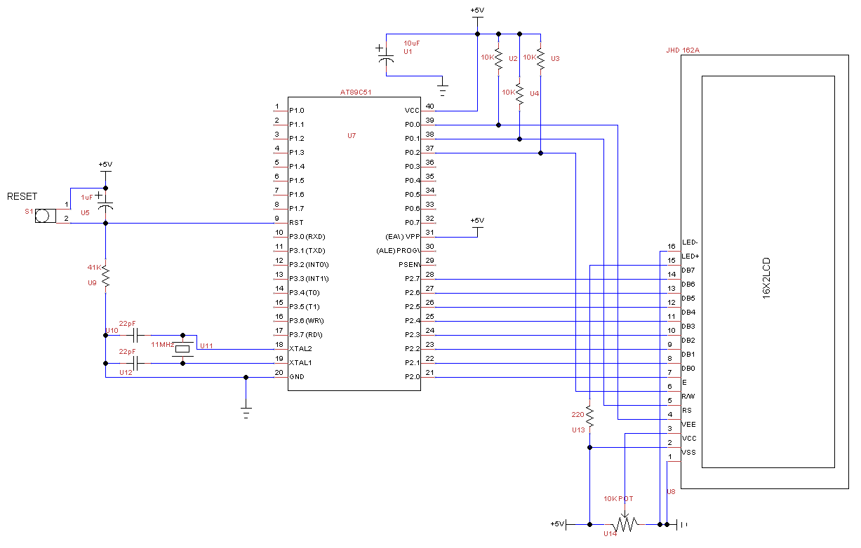
Next you should know how to connect a LCD to any
microcontroller. For our demonstration I'm using Atmel AT89C51. Check the circuit
diagram below for details. Construct this circuit diagram. (Beware wrong
connections on LCD or microcontroller can permanently damage the devices).
Thirdly after constructing you should know some basics on C
programming of the particular controller. For programming 89C51, you need a
programmer. buy options shown here: I use this one , check the link below
You need a keil uVision IDE software (universal compiler for Atmels and ARMs microcontroller) which
will compile your code and give a hex file as output. That hex file has to be
programming into the microcontroller.
And main thing is programming the controller.
There are some instructions you need to know to make lcd
work perfectly. If you know this well, programming is piece of cake.
Learn this commands very well.
You will execute this command first after 50msec delay(LCD
needs a delay at start before sending commands).
1. First you Set
RS= 0, R/W=0, EN=1; And then write this hex code on data bus given below:
D7
|
D6
|
D5
|
D4
|
D3
|
D2
|
D1
|
D0
|
0
|
0
|
1
|
DL
|
N
|
F
|
0
|
0
|
Where D7 is Most significant Bit [MSB] and D0 is Least
Significant Bit [LSB].
Write 0's and 1's as shown on the bit value but chose the
ones which are named DL, N, F
DL means Data Length : If '1' is put on D4 bit then It
considers 8-Bit data bus. (Which is what
we need exactly to work with. If '0' is put then it considers 4-Bit data bus.
And our 8bit data will never be recognized. So choose it wisely.
N means Number of Display lines: You can chose maximum 2
lines since its 16x2 LCD. The internal controller of LCD supports maximum 2
lines for alpha numeric LCD's like this. For 16x4 LCD there are 2 internal
controllers. Each supporting 2 lines. So Line mapping is tricky there.
On 16x2 LCD: when '1' is put in place of N , 2 lines are
selected for use. When '0' you can use only 1 line for displaying data.
F means Font size. when
'1' is put it displays 5x7 pixel font. When '0' is put it displays 5x10
pixel font.
And main thing. When you send this data on the databus of
LCD. You have to latch using EN signal 4times. With overall delay atleast greater than 30 milli seconds.
If you send this instruction below: your hex code will be
0x38. Eg.
D7
|
D6
|
D5
|
D4
|
D3
|
D2
|
D1
|
D0
|
0
|
0
|
1
|
1
|
1
|
0
|
0
|
0
|
This instruction will Enable 8-bit Databus, Set 2 lines, and
Select font size 5x7.
For next, You have to execute this instruction.
D7
|
D6
|
D5
|
D4
|
D3
|
D2
|
D1
|
D0
|
0
|
0
|
0
|
0
|
1
|
D
|
C
|
B
|
D means Display On/Off Select: If you put '1'
you will see the characters on screen.
If you put '0' you will never see characters on the screen.
C means Cursor On/ Off select: If you put '1' you will see
the cursor on the screen hence showing you present location where you next data
will be displayed. If you put '0' the cursor will be hidden and your present
location will be hoax(doesn't matter for professional programmer).
B means blinking of Cursor: If you put '1' your cursor will
blink. If you put '0' it will not blink. This instruction will not work if
cursor is turned OFF.
It requires only 1 Latch enable.
If you send this instruction below: hex code = 0x0F
D7
|
D6
|
D5
|
D4
|
D3
|
D2
|
D1
|
D0
|
0
|
0
|
0
|
0
|
1
|
1
|
1
|
1
|
It will display the characters, will display the cursor and
it will blink.
How do I clear the Display after writing characters I
want????
It requires only 1 Latch Enable.
Well use this instruction below: hex code = 0x01;
D7
|
D6
|
D5
|
D4
|
D3
|
D2
|
D1
|
D0
|
0
|
0
|
0
|
0
|
0
|
0
|
0
|
1
|
This code will clear the entire display. And bring your
cursor to position 0. Or home position.
How to write on a particular line????
Use this instruction to select line 1: hex code 0x80
D7
|
D6
|
D5
|
D4
|
D3
|
D2
|
D1
|
D0
|
1
|
0
|
0
|
0
|
0
|
0
|
0
|
0
|
Use this instruction to select line 2: hex code 0xC0
D7
|
D6
|
D5
|
D4
|
D3
|
D2
|
D1
|
D0
|
1
|
1
|
0
|
0
|
0
|
0
|
0
|
0
|
There is also instruction to shift the cursor left and right for Displaying data at particular location on the LCD.
You can check the datasheet of the LCD for mode advanced codes if you want to explore more.
You can check the datasheet of the LCD for mode advanced codes if you want to explore more.
To display
Data on LCD, You have to Change RS=1 after executing above instructions.
For Ascii
codes. Follow the table below:

Display the
ascii table here for LCD: For example M =0100 1101 = 0x4D on this LCD Character RAM.
Now I will
give you the code I wrote to display my name on JHD 162A.
If you
followed the instructions I wrote above. You will understand each and every
line i write here.
Type this
code below in bold black on your c compiler(keil uVision 3):
#include "REGX51.H"
//It contains all the Register, Special register addressing
information
//Go into
REGX51.H if you want to see deep details on 89C51 architecture.
#define RW
P0_1 //This is simple way to assign names to Port Pins; RW is named as Port 0
Bit 1
#define RS
P0_0 //RS is named for Port 0 Bit 0
#define EN
P0_2 //EN is named for Port0 Bit 2
#define DATA
P2 //DATA bus is named for Port 2 (8-bit)
void
delay(int n); //universal Delay routine for your code; can be customised for
your use.
void
s_inst(void); //Send Instruction Function Select routine
void
s_data(void); //Send Data Select routine
void
s_latch(void); // Latch Data/Instruction on LCD Databus.
void
main(void) //Main function
{
int k=0;
char
x[6]="Macjan"; //you can name it whatever you want.
char
y[9]="Fernandes"; //You can name it whatever you want.
RS=0;
//Initialize RS=0 for selecting instruction Send
RW=0; //Select RW=0 to write Instruction/data
on LCD
EN=1; //EN=1 for unlatch. (used at initial
condition)
delay(100000); //some LCDs takes time to
initialize at startup
s_inst(); //Call Instruction Select routine
DATA=0X38; //Send This instruction on Databus
Port 2 on LCD databus.
s_latch(); //Latch this above instruction 4
times
s_latch();
s_latch();
s_latch();
DATA=0X0F;// Send Second Instruction on Port
2.
s_latch();
DATA=0X10; // Set cursor on line 1. Use 0xC0
to write on line 2.
s_latch(); //Latch the above instruction 1
time.
DATA=0X0; //Before changing to write data
select. Make port 2 =0x0 so that LCD receives nothing
s_data(); //Change the input type to
Data.(before it was instruction input)
s_latch();
//Latch the above instruction once.
for(k=0;k<=5;k++)
{
DATA=x[k];
//It will send x[0]='M' as = 0x4D on Port 2.
s_latch(); //Latch the above instruction only
once. Or it will clone each character twice if you latch twice.
}
//to type on
line 2 call instruction routine first then send instruction on port 2.
s_inst(); //Instruction Select
routine called
DATA=0XC0; // Set cursor on line 2.
Use 0x10 to write on line 1.
s_latch();
DATA=0X0; //Before changing to write
data select. Make port 2 =0x0 so that LCD receives nothing
s_data(); //Change the input type to
Data.(before it was instruction input)
//Now it will show Fernandes on line 2.
for(k=0;k<=8;k++)
{
DATA=y[k];
//It will send y[0]='F' as = 0x45 on Port 2.
s_latch(); //Latch the above instruction only
once. Or it will clone each character twice if you latch twice.
}
while(1); //infinite loop after completing
task
}
void
delay(int n) //Universal delay routine
{
int i=0,j=0;
for(i=0;i<=n;i++)
for(j=0;j<=10;j++);
}
void
s_inst(void) //Instruction select routine
{
RS=0;
RW=0;
}
void
s_data(void) // Data select routine
{
RS=1;
RW=0;
}
void
s_latch(void) // Latch routine
{
EN=1;
delay(1000);
EN=0;
delay(1000);
}
Now how to make a custom character?
This is how a
character looks on LCD. There are 8Rows (b0 to b7) and 5Columns (d0 to d4).
I did a example
here to show you smiley called Smile on the character map. The black pixels
means On (1) pixels.
And the pixels
which are not On are (0) pixels. So on
the right side I have shown you the hex representation of a row.
Well to enter a
character in a LCD. You must know the CGRAM AD instruction. Well the below
table is the CGRAM Instruction.
First you Set RS=
0, R/W=0, EN=1; And then write this hex code on data bus given below:
D7
|
D6
|
D5
|
D4
|
D3
|
D2
|
D1
|
D0
|
0
|
1
|
Ad5
|
Ad4
|
Ad3
|
Ad2
|
Ad1
|
Ad0
|
Where Ad0 to Ad5
are address to the CGRAM.
Well Usually we
put the address as 0x000000 in this locations.
Hence it gives
hex value as = 0x40; (0x0100 0000)
If you send this
code as instruction, and then latch it once.
The LCD will wait
for 8byte data for the character.
So you have to
send this 8bytes as one byte latched at a time.
After completion
of 8 bytes transfer in data mode, the LCD will consider you have stored the
character temporarily. And hence you clear screen the LCD using command 0x01.
The LCD has 16 CGRAM registers. You can store 16 Characters. I will show
you simple example to display smiley using above circuit.
#define RW P0_1
#define RS P0_0
#define EN P0_2
#define DATA P2
void delay(int n);
void s_inst(void);
void s_data(void);
void s_latch(void);
void custom_character(char x[64]);//custom character function
void main(void) //Main function
{
char smile[8]={0x00,0x00,0x0A,0x00,0x11,0x0E,0x00,0x00}; //This is taken from the above picture pixel hex representation
RS=0;
RW=0;
EN=1;
delay(100000);
s_inst();
DATA=0X38;
s_latch();
s_latch();
s_latch();
s_latch();
DATA=0X0f;
s_latch();
DATA=0X10;
s_latch();
DATA=0X01;
s_latch();
custom_character(smile);
DATA=0x00; //ASCII address equivalent for your smile character. for next character it will be 0x01, 0x02,0x03,0x04,0x05,0x06,0x07.
//for displaying next custom characters you have to utilize the full array i mentioned in custom character.
//Remember you can write there only once. If you modify your old ones, the screen will get modified too.
s_latch();
while(1); //infinite loop after completing task
}
void custom_character(char x[64])
{
int k;
s_inst();
DATA=0x40; //Send the instruction to set CGRAM address to store your custom character.
s_latch(); //Latch this data once.
s_data();//Enable data mode.
//Next you have to send 8bytes of character data. Do like this below.
for(k=0;k<=63;k++)
{
DATA=x[k];
s_latch();
}
//After 8 bytes transfer you must run a clear screen once, I am having issues in reading data here, so i used this instruction to overcome.
s_inst();
DATA=0x01;
s_latch();
s_data();
}
void delay(int n) //Universal delay routine
{
int i=0,j=0;
for(i=0;i<=n;i++)
for(j=0;j<=10;j++);
}
void s_inst(void) //Instruction select routine
{
RS=0;
RW=0;
}
void s_data(void) // Data select routine
{
RS=1;
RW=0;
}
void s_latch(void) // Latch routine
{
EN=1;
delay(100);
EN=0;
delay(100);
EN=1;
delay(100);
}
// END of program
After writing the Code, Do this keil
settings:
Menu -> Project -> option for
Target1
In device tab select Device Atmen
-> AT89C51
In target tab edit 11Mhz Clock. Tick
on On-Chip Rom.
In output Tab tick on Create
Hex.
No comments :
Post a Comment